One simple programming technique I like to use in PLC logic is what I call the “trap timer.” Maybe there’s a better name, but I’ve often written code for various reasons to “trap” issues- saving a key piece of information for further review when some event occurs. Such is the nature of this technique, although I use it to continuously collect information for analysis. I’ve used this for years, but people always seem surprised when I show them how to do this- both at the simplicity of the logic, and its usefulness. Maybe there are some logic languages that have this function built in, but I haven’t come across this in the brands of processors I’ve worked with. I’ve used the same basic methodology in other types of processors with different types of logic, but the concept is always the same. The goal is to time an action and remember the total time at the end of the action.
In many pieces of equipment or processes, timing is critical. In situations where a cycle proceeds step by step, waiting for a process to change in each step, whether it be a motion, a temperature, a pressure, a mixture, or some other attribute to change states, the time required is often a critical variable. Sometimes alarms occur when the change happens to slowly or too quickly, but rarely do operations measure and track the time it took for a change to occur.
Take a simple box erector. A box is separated from a stack, picked away, opened, has minor flaps folded, then major flaps folded, and then is pushed through a sealer to complete the process. In one machine I’ve dealt with, there are 9 discrete steps. Each step must be completed before the next one begins. The cycle time is the sum of the times for each step. If the erector slows down, it might not keep up with the rest of the line. How does an operator know what is keeping his/her machine from keeping up? My solution is to develop a timing display that shows the operator exactly how long each step is taking. Then the operator and maintenance can determine what intervention to make to get timing corrected. For this to work, however, we need to have times to display. This is where the trap timer comes into play.
For a trap timer to work, you must be able to know when an operation begins and when it finishes. For example, we turn on a solenoid valve that supplies air to a cylinder. The valve stays on until a limit switch changes state. The operation we are watching is the amount of time the solenoid valve is turned on. See the ladder logic example below.
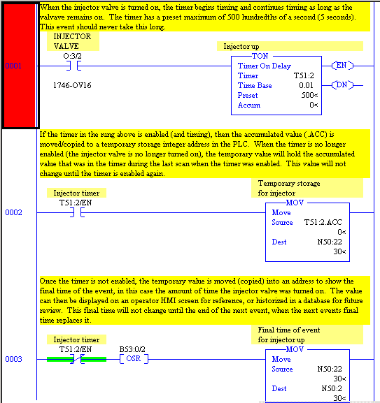
If you aren’t familiar with this type of notation, here is a brief explanation. The timer in the initial rung is a “Timer On-Delay” or TON. It is normally used for delaying actions after a condition has been present for a pre-set amount of time. The pre-set time is contained in the register .PRE. When the condition that enables the timer is true, then the timer accumulates time in the .ACC register. The enabling condition for the timer is shown through the /EN bit. When the accumulated time (.ACC) reaches the pre-set value (.PRE), then the timer is done timing, turning on the /DN bit for the timer. Whenever the enabling condition (/EN) becomes false, the accumulated value (.ACC) is reset to zero and the done attribute (/DN) is turned off, regardless of whether the pre-set value (.PRE) has been reached. There are many variations of timer types and ways to represent them in different processors, but the basic Timer On-Delay (TON) is by far the most common in industrial controls, which is one reason I choose to use it.
In the initial rung (rung 1 in the example), a timer (T51:2) is enabled when the injector valve is on. The time base of 0.01 means the timer is counting in hundredths of a second, so the pre-set of 500 is actually 5 seconds. I chose this because I expect this action to take well under a second to complete and 5 seconds is a time that should never occur, unless something is terribly wrong. In many situations I have worked with, the timer is being used as an alarm- if it enabled until the timer is done, then the process has a problem and the operator needs to attend to it. If that is the case, the timer can serve two purposes. The first rung can be the timer, which is also monitoring for an alarm, and the next two rungs trap the length of time it takes for the activity to occur the vast majority of times when an alarm doesn’t occur.
For those not familiar with PLC ladder logic, the processor executes commands in the ladder from top to bottom, one rung at a time. When all the rungs have been scanned and executed, changes in outputs are made in the physical terminals and changes in input values from the physical terminals are put into the processors memory and the next program scan is started. The total time for a scan on modern PLCs are often around a millisecond or less, so a timer that is timing in hundredths of a second may go through 10 or more program scans before increasing the accumulated value. Older processors may have scan times of several milliseconds, depending the size of the program. For our example, consider that the logic in the ladder is executing hundreds of times per second, over and over again.
The second rung (rung 2 in the example) uses a move command (MOV) to move (actually copy) the accumulated value of the timer into a storage integer (N50:22). (The N in the address stands for iNteger- I know, integer starts with an I, but I is reserved for Input.) This move happens only when the timer is enabled, but happens every program scan of the processor when the timer is enabled. The accumulated value in the timer (.ACC) is not changed by the move command as it really moves just a copy of the value, and continues to accumulate time while the timer is enabled. When the timer is no longer enabled, no move occurs and the stored value remains the same, while the accumulated value (.ACC) of the timer is reset to zero.
The last rung shown (rung 3 in the example) also uses a move (MOV) command. This rung is true only once in the cycle, the first scan when the timer is no longer enabled. Once the activity we have been timing is completed, the temporary value (that we stored in a previous scan in the middle rung) is moved/copied to a final storage location (N50:2) for future use. This is the value we are interested in, and it will stay in this location until another cycle of the activity we are timing occurs. While the next cycle is occurring, the value of the previous cycle remains in the final storage location. Only when the cycle is complete does the value change.
Let’s review what physically is happening as this trap timer logic occurs. In our example, elsewhere in the logic, it is determined that the Injector Valve should turn on. When this occurs, the initial rung becomes true and the timer is enabled and starts timing. As the injector is moving to its destination, time accumulates in the .ACC register of the timer, and the temporary storage integer location (N50:22) has the same value immediately moved/copied to it. The final value contains the last cycles time of 31 hundredths of a second. After 29 hundredths of a second, the injector physically triggers a limit switch. The logic then turns off the output (O:3/2) to the injector valve. Since the enabling condition to the timer is now false, the timer is no longer enabled and the accumulated value (.ACC) is reset to zero. In the middle rung, nothing happens this scan because the enabling condition (the timer being enabled) is false, so the accumulated value is not moved and the stored value (N50:22) remains at 29. Now, the final rung is true, as the timer is not enabled and this is the first scan that it is not. The stored value of 29 is moved to the final value location (N50:2) with a value of 29 replacing the 31 from the last injector cycle. In future scans, nothing happens on any of the rungs as all are false, until the next time the injector valve is turned on.
The end result of this logic is that the stored value location (N50:2) always contains the timed value of last completed action.
So what? What do I do with a trap timer?
As with many nifty programming techniques I use for data collection, the power isn’t in the programming, it’s in what is done with the data that emerges. I use trap timers for all kinds of analysis. Here’s a few ways to put them to work.
- Display- maybe you have one critical item that is event driven on your machine or process. Getting cycle time right is critical. Just display the end result of the trap timer on a display for your operators or maintenance team. The workers can then act to adjust timing and see immediately the impact of their changes.
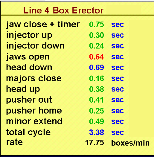
If the process is a series of events, then time each event and make a display with each event’s time listed. I do this on many pieces of equipment where many events are required to complete a machine cycle. Below is a display example of the box erector from the logic above.
- Set warning limits or alarms for timed values that are too fast or two slow. Often just displaying a time isn’t enough information. People need a context for the data for it to be useful. Most displays allow you to set alarm limits for values that are too high or too low. You can then trigger alarms on the display, or color code a time so workers know when to pay attention to a value. For example, if a motion should take 1.5 seconds, but you know that a time faster than 1.2 seconds will damage the equipment, while a time greater than 1.8 seconds will prevent the process from making rate, you may set a low warning alarm at 1.3 seconds and a high warning alarm at 1.7 seconds.
In the example above, note the time for jaws open is red (too fast), while the head down time and total are blue (too slow). These colors come from alarm limits in the display and display color choices picked when making the display screen.
Years ago, I asked a programmer for an equipment vendor during a design review to put in trap timers and build a display screen like this one for a machine they were building. It probably took me 30 minutes of conversation to convince him to do it, as he saw it as a lot of work, but since I was the customer he agreed. When I came back a few months later for our factory acceptance test, he pulled me aside and told me how much help the screen had been for the other designers in lining out the equipment. The machine had many motions that had to be completed before the next motion could happen. By timing each one, the designers had been able to see which motions were the biggest contributors to the overall cycle. They changed a few components to speed up the slowest moves, and as testing continued, they spotted changes in times that indicated premature wear, which allowed them to make other changes. The programmer said he would never make another indexing machine without this valuable tool. When the plant installed the line, the operators monitored this timing screen constantly to keep the line at rate.
- Develop centerline settings for each production set-up. Maybe you have different products that require different timing. Once you know the optimal settings for each motion for each product, you can dial it in my adjusting motions and seeing the impact on the operational display.
- Store timed values in a historian database for trending and later review. Almost any data equipment generates is good to historize for future reference. That is particularly true with trap timer values. Like a lot of data, I store this information just in case I need it. Why would I need it you ask? Well, when people come to me and tell me that there is a problem with a piece of equipment not running fast enough and that it has been that way for a long time, I can pull up data and see when the problem actually started. Has it changed gradually? Did it happen at a specific point in time? If so, what else happened then? Maybe someone changed a part and didn’t get the settings adjusted correctly. Maybe a material supplier made a change. Maybe a part is worn and needs replaced. The trend of historical data often helps determine what happened.
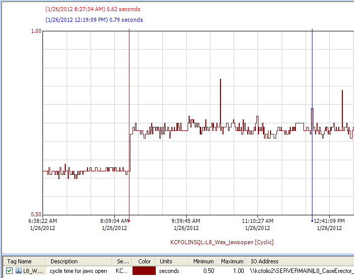
Look at the example below of a trend from a historical database. Before 8:30, the jaws were opening in about 0.62 seconds. After 8:30, the jaws took around 0.73 seconds. At three different times, the jaws took much longer to open, including a highlighted event at 12:19 that took 0.79 seconds. What does this tell us? Obviously, something changed at 8:30. Did someone change a flow control? Did something break? The later spikes are likely unique issues with materials- a box with excess glue that didn’t open cleanly.
- Do statistical analysis on the data to determine more about the situation. If times vary from cycle to cycle, maybe it helps to average the data to give workers a better sense of how a process is performing over a longer period. One easy way is to use an Exponentially Weighted Moving Average, a calculation that constantly recalculates without storing much data. I’ll cover the benefits and details of that method and other similar statistical calculations in another posting, but think of averaging as a way to eliminate the noise of variation.
Speaking of variation, calculating standard deviation of a period of data can be helpful to compare to other periods of time. Why? Consider the fact the many equipment components don’t fail all at once, they slowly wear over time. Pneumatic components- solenoids, air cylinders, and the like have wear patterns that are particularly hard to detect. As seals wear, parts stick ever so much more as time passes. Motion takes longer, but more importantly motion varies more. If you measure this variation and look for increased variation, over time you can detect when a component is starting to fail way before it is noticeable by the naked eye. It’s a subtle, but very powerful predictor that you can use in a structured Predictive Maintenance program. Take baseline data when the parts are new and then sample the data periodically to sense changes. With time, you’ll learn when variation increases enough to impact the performance of your process and be able to schedule replacement on a planned basis before performance is sacrificed.
These are five things I commonly use trap timers for and you may have many others. It all starts with collecting a simple piece of information that can be trapped in a few rungs of logic. This isn’t hard, but by now I hope you can see the power of this simple technique.
Sometimes, the logic of an event isn’t as predictable. Maybe there is bounce in the motion that causes double flagging of a sensor. Or maybe you want to exclude times when equipment jams or delays and doesn’t work as planned. In these cases, limiting the values allowed to move into the permanent storage register keeps errant data from being stored.
Take a look at the example below. Say you have an event that normally takes 2.5 seconds and if isn’t complete in 5 seconds a fault occurs. Also, the logic for the timer comes true for a split second during the normally idle portion of the cycle. You decide that you want to know how often the event is faulting out for too long of time, but you don’t want to get a nuisance 0.05 time right after the correct time of 2.5 seconds every cycle. By inserting a comparison condition in the logic, in this case a greater than comparison requiring the time to be at least 0.10 seconds to be moved, only longer times are trapped, and shorter false events are ignored.
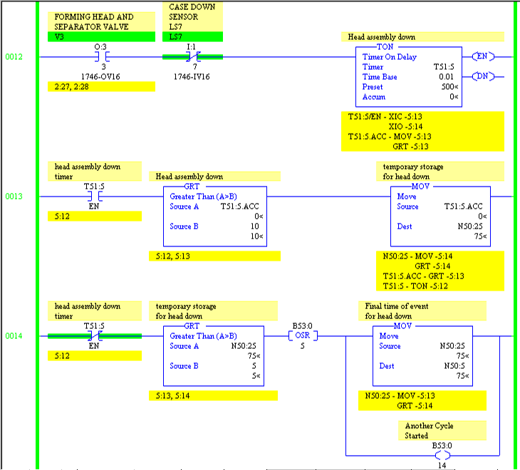
There are many other special circumstances that may cause you to alter the logic slightly. You can shorten the logic on many processors by combining two of the rungs. In processors that don’t use ladder logic, you have to do the same type of logic in the language available. The concept is always the same- trap the time it takes for an event to occur and save it in a location to access for further reference. I’ve used this technique in many ways over the past few decades and find it one of my go-to techniques in many situations.
Share your success stories with this technique in the comment section below. Happy trapping!


